Staircase Perspective – Mastering Linear Perspective for Stair Flights: Complete Technical Drawing and Architectural Representation Tutorial

Description:
Staircase perspective (or stepped perspective) is an essential technique in technical drawing, architectural illustration, and spatial design, enabling the accurate representation of stair flights with geometric precision and realistic depth. This method, based on one- or two-point linear perspective, combines proportional division of risers and treads with convergence toward vanishing points (VP) to create a convincing three-dimensional representation. Ideal for architects, illustrators, interior designers, and visual arts students, this tutorial breaks down the classic staircase perspective diagram step by step, explaining each element, its function, and how to apply it in real projects. You’ll learn how to construct inclined staircases, calculate equal divisions, locate vanishing points, and avoid common distortion errors.
Introduction: What is Staircase Perspective?
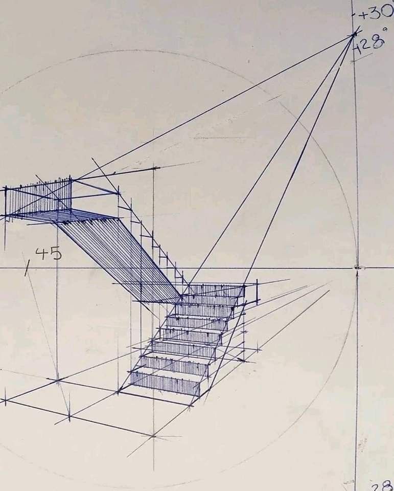
Staircase perspective is primarily used to draw straight inclined staircases viewed from an elevated or frontal observation point. Unlike freehand perspective, this system uses parallel guide lines in the actual plane (treads and risers) that, when projected toward the vanishing point (VP), generate an optical illusion of depth. The diagram shown illustrates a staircase in one-point perspective (central VP), with precise geometric divisions ensuring uniform proportions throughout the flight.
This method is especially useful in:
- Architectural plans
- Interior illustrations
- Storyboards and concept art
- 3D modeling as a technical reference

Step 1: Establish the Vanishing Point and Horizon Line (HL)
Begin by defining the Horizon Line (HL), which represents the observer’s eye level. In the diagram, this line is marked horizontally in the upper middle section.
- VP (Vanishing Point): Located at the center of the HL, it is the point toward which all depth lines (treads and side edges of the staircase) converge.
- VP-S1 and VP-S2: Secondary vanishing points at the vertical ends of the HL. They serve as references for inclined parallel lines (such as handrails or side skirting).
Technical Note: In real staircases, treads are parallel to each other in plan, but in perspective, they converge toward the VP. Handrails, being parallel to the ground in section, also converge toward VP-S1 and VP-S2.
Step 2: Draw the Height of the First Riser
The riser is the vertical face of each step. The diagram indicates:
“Height of the first riser”
This is the vertical starting point. From the ground (base of the drawing), draw a vertical line representing the actual height of the first step (typically 15 to 18 cm in standard architecture).
- Mark this segment as A → B.
- From point B, project a line toward the VP to define the first tread (horizontal surface of the step).
Step 3: Equal Division of Risers – Geometric Method
The main challenge is dividing the stair flight into risers of equal height along an inclined line. The diagram shows two methods:
Method 1: Direct Division from the VP
- From the VP, draw equidistant lines that intersect the inclined line of the staircase.
- These lines represent the equal divisions of the risers in the next stair flight.
- Each intersection defines the top edge of a riser.
Method 2: Lines Parallel to Treads (VP-S1 and VP-S2)
- From VP-S1 and VP-S2, draw lines parallel to the treads (horizontal surfaces).
- These lines intersect the sides of the staircase (skirting or railings) and serve to locate the tread flights and handrails.
Diagram Key: “VP-S1 and VP-S2 also serve for other lines parallel to the inclined lines connecting the tread flights, for handrails and skirting.”
Step 4: Progressive Construction of the Stair Flight
Follow this construction sequence:
- Ground line and inclined line: Define the staircase angle (typically 30° to 40°).
- First riser: Vertical from the ground.
- First tread: Line from the top edge of the riser toward the VP.
- Geometric repetition:
- From the VP, draw equidistant lines intersecting the inclined line → locate the start of each new riser.
- From each intersection, drop a vertical (riser) and project toward the VP (tread).
- Sides and handrails:
- Connect the ends of the treads with lines toward VP-S1 and VP-S2 to form the skirting.
- The top handrail follows a line parallel to the incline, intersected by divisions from VP-S1/VP-S2.
Step 5: Visual Verification and Adjustments
Once the structure is complete:
- Verify that all treads converge to the VP.
- Ensure risers are parallel in the actual plane (though they may appear inclined in perspective).
- The divisions must appear visually uniform to the observer’s eye, even if actual distances decrease due to perspective.
Pro Tip: Use a ruler and compass on paper, or precision tools in software like AutoCAD, Rhino, or Procreate (with perspective guides).
Practical Applications
| Use | How to Apply This Method |
|---|---|
| Architectural plans | Represent staircases in sections and perspective elevations |
| Interior illustration | Create depth in livable spaces |
| Concept art / video games | Design realistic environments with stairs |
| Models and renders | Use as a base for precise 3D modeling |
Common Mistakes and How to Avoid Them
| Mistake | Solution |
|---|---|
| Uneven tread sizes | Use geometric divisions from the VP |
| Flat staircase without depth | Ensure strong convergence to the VP |
| Misaligned handrails | Use VP-S1 and VP-S2 for parallel lines |
| Inclined risers | Keep risers vertical in reality; only appear inclined in perspective |
Conclusion: Master the Staircase, Master the Space
Staircase perspective is not just a drawing technique: it is a visual communication tool that conveys height, movement, and structure with mathematical precision. By mastering this system, you can confidently represent any staircase — straight, L-shaped, U-shaped, or spiral (with adaptations) — with realism and accuracy.
Recommended Practice: Draw 10 staircases from different angles and distances to the VP. Start with 5 steps, then increase to 12. Compare with real photos to refine your eye.
Additional Resources Suggested:
- Architectural Graphics – Francis D.K. Ching
- Perspective for Artists – Ernest Norling
- Perspective templates in Procreate / Clip Studio Paint
Share your version in the comments! Tag your drawing with #StaircasePerspective and join our technical artist community.
ARQ. © – School of Technical Drawing and Representation